CHAPTER FIVE
While 50-60% relative humidity levels are ideal for patron comfort and health, they are much higher than in traditional spaces in winter. In cold climates, it is very common to humidify in order to get the humidity levels up to 30-40%. An indoor pool and humidified space can experience condensation problems and serious damage to the building structure in cold weather if they are not designed properly.
Condensation is a major concern for all types of building construction. Condensation triggers a destruction process, as it leads to the growth of mold and mildew. If allowed to occur inside the building walls or roof, condensation will cause deterioration and can devastate the structure by freezing in winter.
It is critical that condensation be avoided at all costs.
The building design and construction must be appropriate to house an indoor pool and must be suitable for 50-60% relative humidity year round.
A successful design will identify and blanket building elements that have low R-values (typically exterior windows) with warm supply air to prevent condensation. Window frames and emergency exit doors must also be thermally broken to avoid condensation.
DEW POINT TEMPERATURE
Condensation forms on surfaces when surface temperatures are lower than the dew point of the surrounding air.
The first step in condensation control is to establish the space dew point temperature based on the desired space conditions. With that information, the designer can establish potential condensation spots in the building. A pool’s indoor design dew point will typically range from 62-69°F (82-84°F 50-60% RH). Contrast this to a typical space in winter that might be 70°F 40% RH, which has a 45°F dew point.
Pools have a much higher likelihood of condensation because of both an elevated space temperature and slightly higher relative humidity, resulting in a very high dew point.
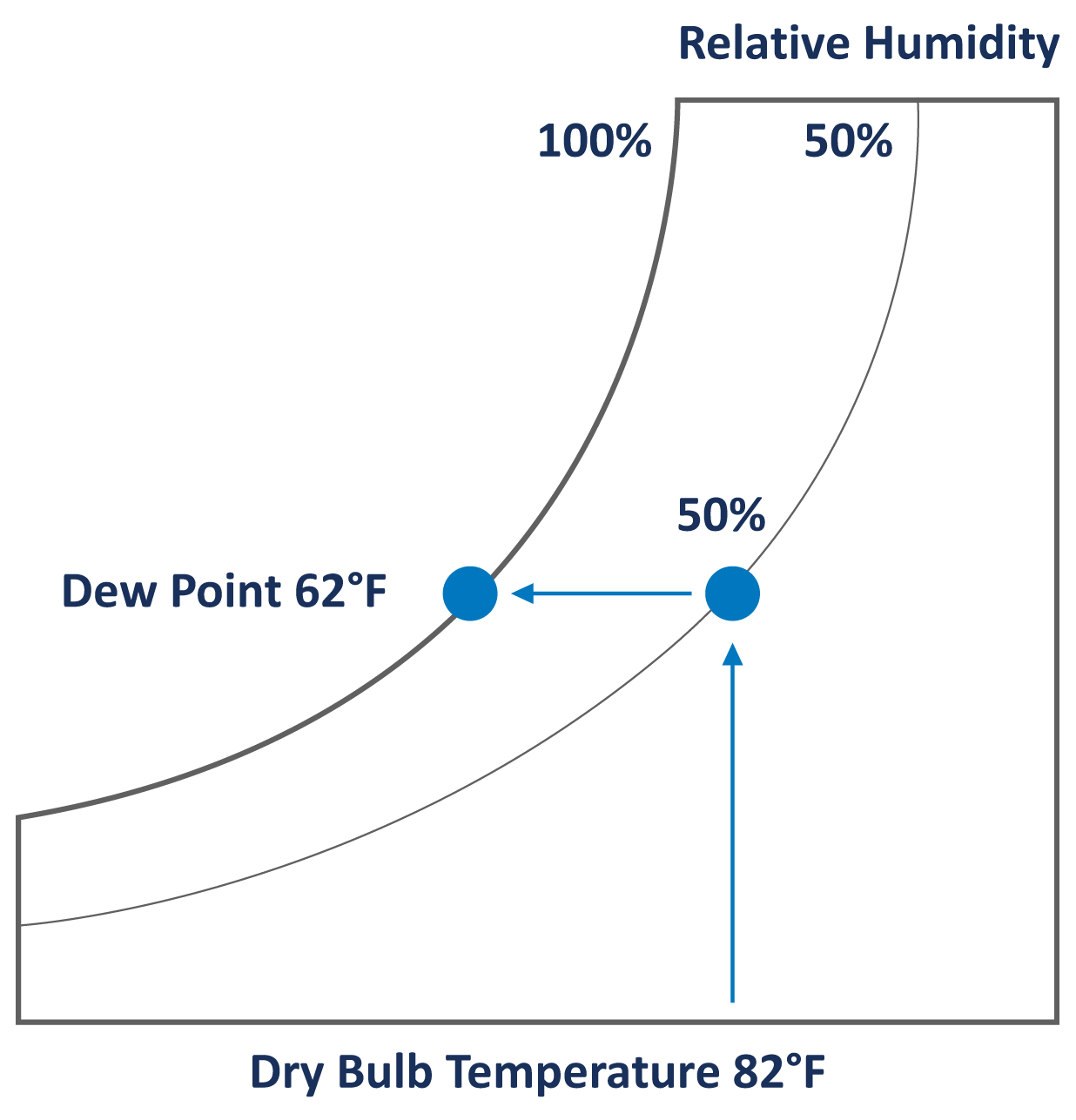
These are building elements with low R-values that will have an inside surface temperature below the dew point at winter design condition. Most importantly, the dew point also establishes where to locate the vapor retarder in the wall. Figure 4 shows that a typical pool design of 82°F 50% RH has a dew point of 62°F.
Therefore, any surface with a temperature below 62°F will condense moisture.
FIGURE 4: DEW POINT TEMPERATURE
VAPOR RETARDER
A vapor retarder is a material that restricts the rate of water vapor diffusion through the ceilings and walls of a building when below dew point temperature occurs. Figure 5 illustrates how failure to install the vapor retarder in the proper location will result in condensation within the structure. Condensation in the walls or roof can lead to structural failure. A vapor retarder should be sealed at all seams.
FIGURE 5: DO NOT BUILD AN INDOOR POOL WITHOUT A VAPOR RETARDER
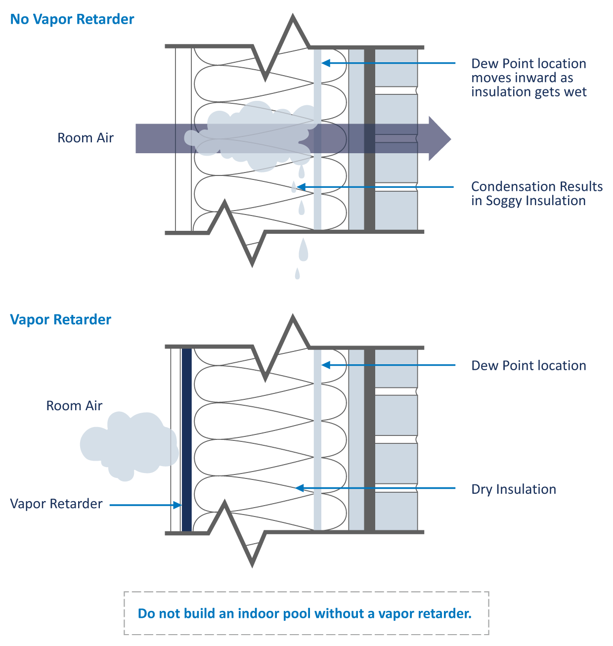
It is important to ensure the entire pool enclosure design (walls and ceilings) has a vapor retarder in the correct location. Care must be taken where walls and roof and walls and floor meet to ensure there is no breach in the vapor barrier.
A properly located and installed vapor retarder is the only means of protecting a building structure from vapor migration that results in moisture damage.
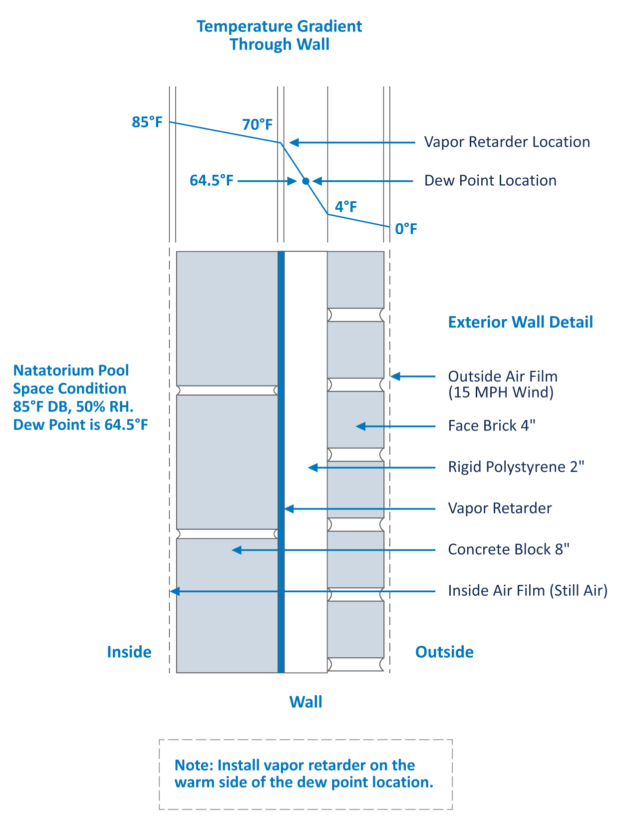
Figure 6 is an example of a wall detail with its temperature gradient. This exercise allows the designer to identify the dew point temperature in the wall and where the vapor retarder must be installed.
FIGURE 6: POOLS ARE DIFFERENT – INSTALL THE VAPOR RETARDER ON THE WARM SIDE OF THE DEW POINT
WINDOW DESIGN
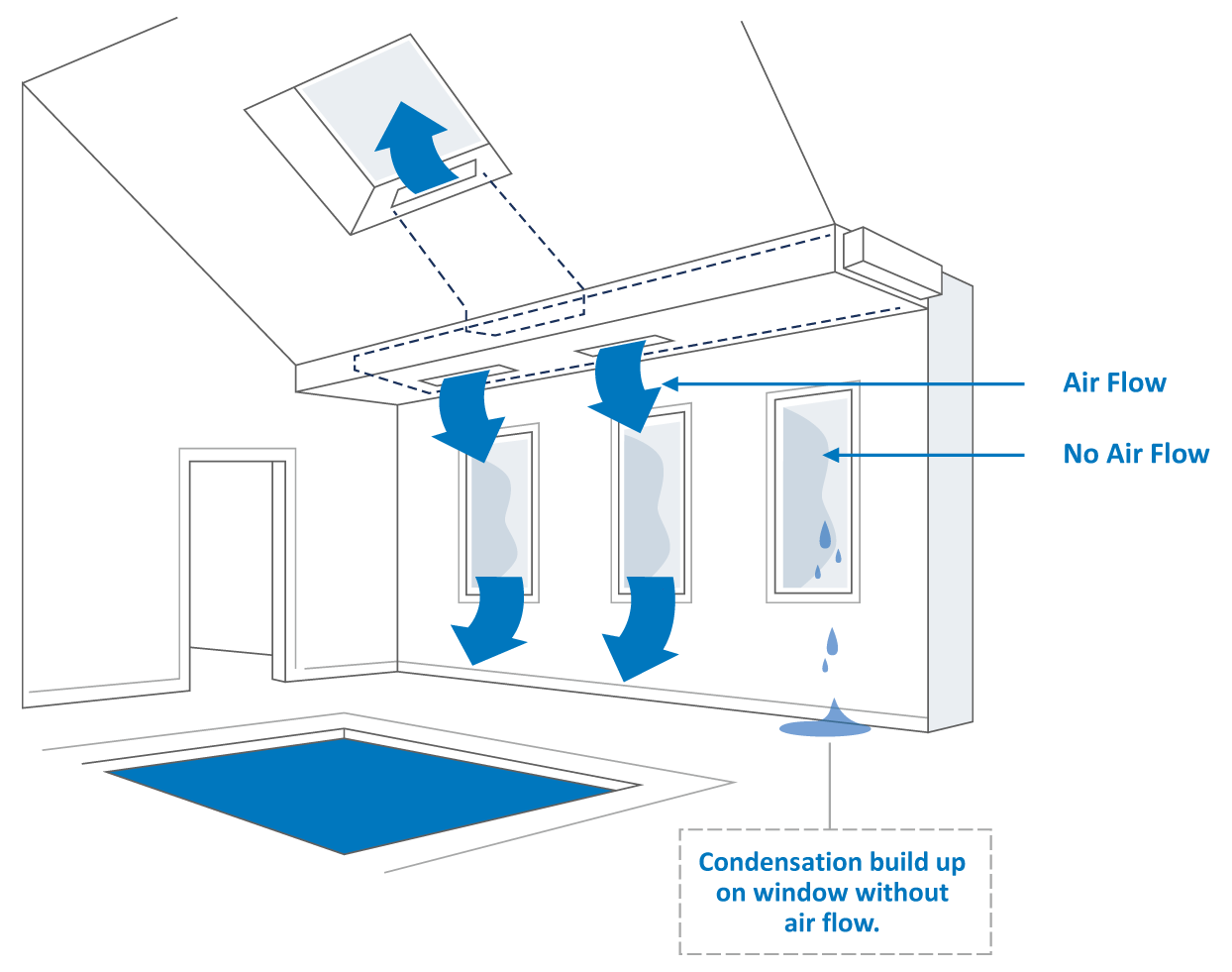
Windows have a relatively low R-value and, as a result, will have surface temperatures below the pool room dew point when outside temperatures are cool. Exterior windows will develop condensation on the first cold day unless preventative measures are taken. The solution to the condensation problem is to fully blanket every part of the window with supply air from the HVAC system. It is critical that no section be missed, or the window will get cold and condense.
FIGURE 7: WINDOW DESIGN
AIR DISTRIBUTION
Since exterior windows and exterior doors are a primary condensation concern, it is extremely important that the supply air is focused in these areas. The warm air from the dehumidifier will keep the window surface temperature above the dew point temperature and in turn, ensure the windows and exterior doors remain condensation free.
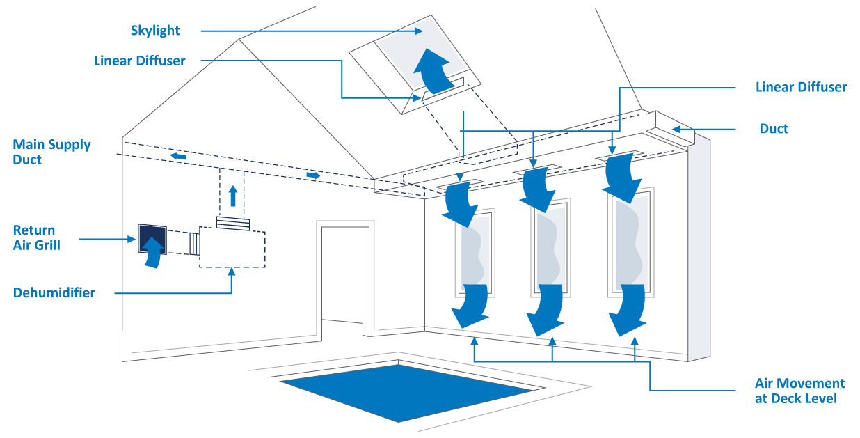
There are five basic steps to laying out the ductwork for the best air distribution:
- Supply air to the breathing zone at the deck level and water surface.
- Supply air to exterior windows and doors.
- Supply air to the remainder of the room to ensure there are no stagnant areas.
- Locate the return duct where it will optimize the entire airflow pattern.
- Prevent air short-circuiting by avoiding supply air diffusers near the return grille.
Figure 8 illustrates good air distribution practices.
FIGURE 8: PERIMETER DUCT LAYOUT
All air distribution systems should:
- Satisfy ASHRAE design requirements and local codes.
- Supply at least 4-6 volumetric air changes per hour.
- Blanket exterior windows, exterior surfaces, and other areas prone to condensation with supply air. A good rule of thumb is 3-5 CFM per ft2 of exterior glass.
- Locate the return grille to enhance the overall air pattern within the room.
- Select grilles, registers, and diffusers that deliver the required throw distance and the specified CFM rating.
- Introduce outdoor air per local codes and/or ASHRAE Standard 62.
- Maintain a negative pressure in the space with an exhaust fan.
- Have an air balance performed.
GENERAL RECOMMENDATIONS:
- Galvanized sheet metal ducts are acceptable in most installations.
- A below-grade duct system should use PVC or plastic-coated galvanized spiral pipe to avoid deterioration.
- Stainless steel duct and hardware should be avoided as they are readily attacked by chlorine.
- Fabric duct is an excellent choice of duct material for a natatorium.
- The duct material should not allow air to leak.
- The location of supply grilles and overall duct layout should be exactly the same as with a metal duct.
- Ductwork that passes through an unconditioned area should be insulated on the exterior.
- When applicable, locate exhaust fan air intakes as close to the whirlpool as possible.
- To prevent excessive vibration noise, install neoprene flex connectors when attaching ductwork to the dehumidifier. Acoustic insulation on the duct close to the unit may also be a consideration.
- Skylights require significant airflow to avoid condensation on their surfaces.
